The MIDI Looper
 The Looper has a different approach than the Midi Switch. The Looper was designed to integrate conventional FX units (like distortion, chorus, wha, etc.) into a (midi) controlled setup. Of course, you could do that with the midi switch, too. But the looper takes the job of several devices: Midi pedal (sends a midi program change with each patch change), effects looper (put your analogue stomp boxes in the loops) and amp channel switcher. The Looper has eight switched outputs which can either be used as loops or switches (e.g. 6 loops, 2 switches), plus one midi out.
There are fourty patches, each can be programmed with different output settings. The patches are arranged as 4 patches in 10 banks. With each patch change, the Looper sends a midi program change command on midi channel 1. So, on patch one you have midi program 1, on patch 2 you have midi program 2, etc.
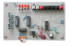 Building the Looper is a bit more complicated than building the switch, but only because the Looper needs some more components. The circuit is also based on the PIC 16F84 micro controller, with some peripheral components for display and outputs. The Looper needs a stable 5V power supply. Note that you must use a crystal with a frequency of exact 4MHz, otherwise the midi output does not work.
If you do not have a PIC programmer or someone who can do the programming for you, you need to build a programmer (of course you can buy a programmer, but that’s not the DIY idea). In fact, programming the PIC controller is the most complicated thing about this project , but maybe you will be doing more PIC projects anyway. I use the SPRUT programmer, there are lots of resources on the web, even for good programming software, and it’s all for free.
 How to use the Looper:
- Make all connections (audio signal, midi)
- Power up the Looper
- The Looper performs a self test (counts from 0-9 on display)
- The Looper selects Bank0, Patch1 (midi program 1)
- Now you can step through the patches / banks
If you want to edit a patch:
- Select the patch
- Press Edit/Store button once (“Edit”-LED lights up)
- Set the outputs with the according switches
- Press Edit/Store button again (“Edit”-LED turns off)
- Now your settings for this patch are stored
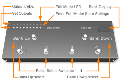
If you take a look at the schematics you will note that some buttons have double functions. In normal (Play) mode (patch select) Switch1 is “Bank down”, Switches 2-5 are Patch1-4, Switch6 is “Bank up”.
In edit mode, Switches1-8 toggle the state of each output. You should connect 6 footswitches in parallel to Switches1-6, so you can use the Looper with your feet in normal (Play) mode.

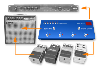
This is my looper setup: The looper control module has been built into an recycled Boss FC-50 MIDI footcontroller. There are four audio loops, which have been moved to a separate aluminium box (above footcontroller). The Looper controls three stompboxes (2xdistortion, chorus), it switches the Line6 M5 into/out of the signal chain and additionally sends MIDI program changes to the Line6 M5 in order to change presets (delay, phaser, reverb, etc.).