The Midi Switch
There now is an up-to-date MIDI Switch which is based on the Arduino platform. Click here fore more info.
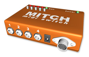 This is my first guitar midi project that was based on the PIC16F84 micro controller. It is a simple midi switch that converts midi program messages into (programmable) analogue switch outputs. As an example, this enables you to integrate non-midi amps with conventional footswitches into midi controlled setups. There are a lot of commercial units like these on the market, but sometimes you want to build one yourself, because it is easier to customize, cheaper or more fun.
You can use as many midi switches in your setup as you like. Each switch provides four outputs which can be used as switches or loops (this depends on your design). Each midi switch can be set to respond to one of the 16 midi channels. Currently there is no midi omni mode function. There are 128 patches (one for each midi program number), and you can edit&save an individual output configuration for each patch.
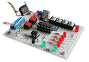 Building the midi switch is quite easy. Most components are fairly standard (apart from the microcontroller which needs to be programmed with the midi switch software). Make sure that you use the opto coupler types specified in the schematic, otherwise the switch might not work. The switch needs a stable 5V power supply; if you have more than one switch, you can use them with one supply.
If you do not have a PIC programmer or someone who can do the programming for you, you need to build a programmer (of course you can buy a programmer, but that’s not the DIY idea). In fact, programming the PIC controller is the most complicated thing about this project , but maybe you will be doing more PIC projects anyway. I use the SPRUT programmer (www.sprut.de), there are lots of resources on the web, even for good programming software, and it’s all for free.
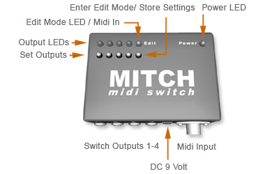 How to use the midi switch:
- Make all midi connections
- Select the midi channel before powering up the switch (see table)
- Power up the switch
- Send a program change command to the switch (Edit/Midi LED lights up shortly)
- Press the “Edit”-key (Edit/Midi LED lights up constantly)
- Set/Unset the outputs by pressing the “Output”-keys
- Press the “Edit”-key again (Edit/Midi LED turns off; your settings are saved)
- Note that the midi switch does not receive any midi messages in Edit-mode
MIDI channel selection / DIP switch settings:
MIDI Channel | SW 1 | SW 2 | SW 3 | SW 4 |
|---|---|---|---|---|
| 1 | OFF | OFF | OFF | OFF |
| 2 | ON | OFF | OFF | OFF |
| 3 | OFF | ON | OFF | OFF |
| 4 | ON | ON | OFF | OFF |
| 5 | OFF | OFF | ON | OFF |
| 6 | ON | OFF | ON | OFF |
| 7 | OFF | ON | ON | OFF |
| 8 | ON | ON | ON | OFF |
| 9 | OFF | OFF | OFF | ON |
| 10 | ON | OFF | OFF | ON |
| 11 | OFF | ON | OFF | ON |
| 12 | ON | ON | OFF | ON |
| 13 | OFF | OFF | ON | ON |
| 14 | ON | OFF | ON | ON |
| 15 | OFF | ON | ON | ON |
| 16 | ON | ON | ON | ON |
If you are going to build a PIC programmer yourself, then you should consider the following web sources:
http://www.sprut.de/electronic/soft/pbrenner.htm
(Excellent german website with programmer and software)